The half-edge data structure
The half-edge data structure (HDS), also doubly-connected edge list
(DCEL),
is a data structure constructed to represent graphs, discrete surfaces and polytopes.
In particular it encodes all the structural and combinatorial information of a given graph or surface.
These information are stored in instances of vertices, edges and faces.
As the name suggests the edges play a special role.
Every combinatorial edge is represented by two directed half-edges, each pointing at one of the incident vertices.
Furthermore, each of the half-edges belongs to a unique face (or None if the edge is a boundary edge)
which allows simple and efficient ways to handle and modify surfaces.
Not all half-edge instances must be topological surfaces but since this is often desired and also needed for visualization
in Blender this can be verified within this package, as explained in the section Validating a surface.
Anyhow, by abuse of terminology, the main class of the half-edge package, and often instances of it, are called surfaces.
The very basics and a simple half-edge surface
We start by initializing an instance of the ddg.datastructures.halfedge.surface.Surface class that can be accessed
using
>>> import ddg
>>> s = ddg.halfedge.Surface()
The instance s is a surface with no edges, vertices or faces given yet.
Using the class methods add_face() and glue() allows a simple extension
of the surface s. New vertices and edges are automatically initialized and linked to the surface.
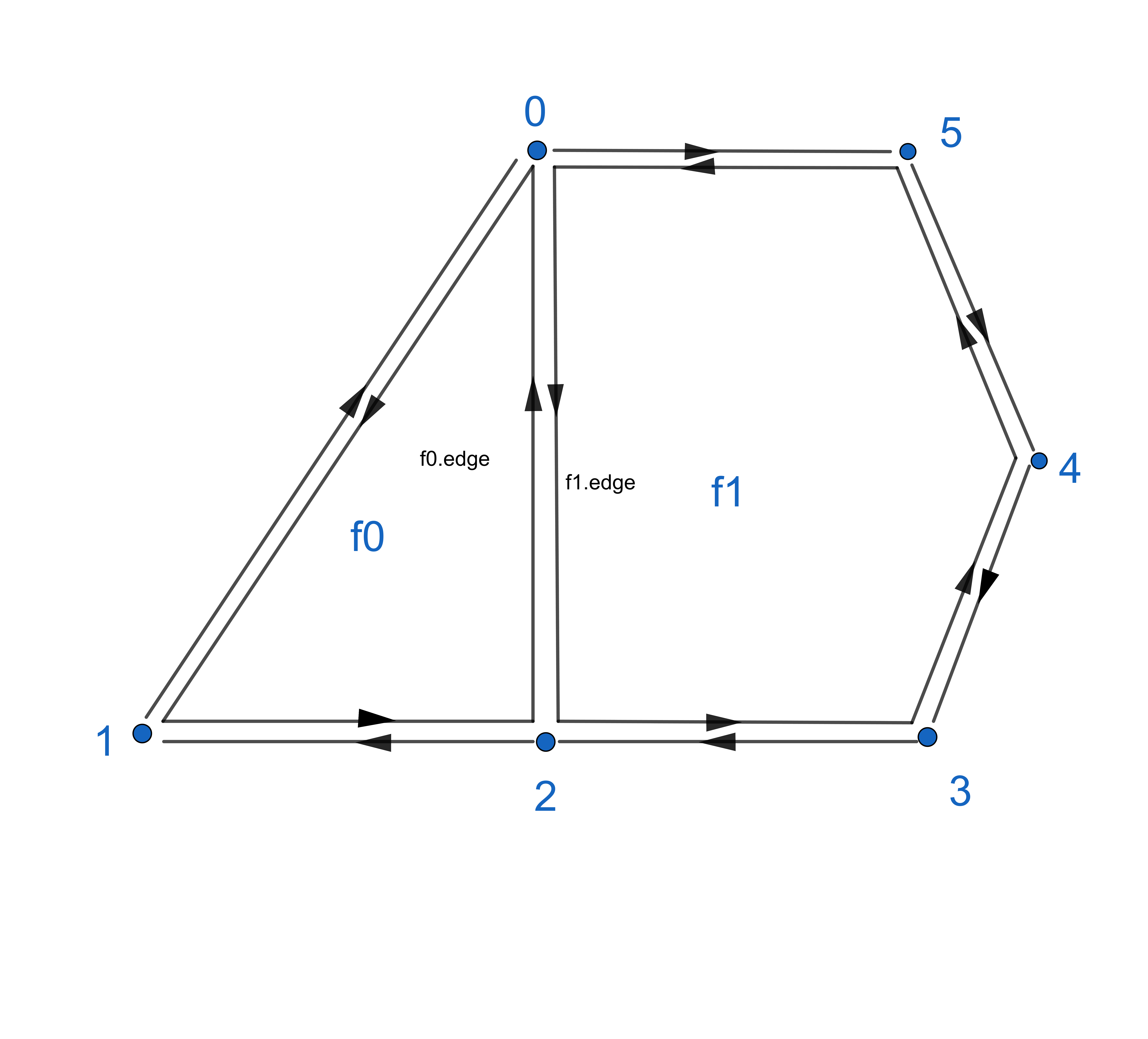
>>> f0 = s.add_face(3)
>>> f1 = s.add_face(5)
>>> s.glue(f0.edge, f1.edge)
The above results in a purely combinatoric surface with 2 faces, 14 edges and 6 vertices.
Faces, edges and vertices are represented as classes stored in s.faces, s.edges and s.verts.
The objects themself posses different attributes, depending on the cell type:
- faces:
edge
index
- edges:
opp
nex
pre
head
tail
face
index
- vertices:
edge
index
For a face f the attribute f.edge points to a random half-edge belonging to the face and for a vertex v the attribute
v.edge points to a random half-edge that points to the vertex.
Taking a closer look at the half-edges of a surface one sees, that the union of all half-edges consists of disjoint oriented loops
of half-edges. For every edge e the attributes e.pre and e.nex allow iteration though these loops.
The “inner” of such a loop either consists of a face of s or is empty. This is represented by each edge attribute e.face that either
returns the face that is enclosed by the corresponding edge loop or returns None if the edge is a boundary edge.
Eventually half-edges are still representing the connection between two vertices, two oppositely oriented half-edges
representing one combinatorial edge. The attribute e.opp allows switching between two such half-edges connecting the
vertices v1 = e.head and v2 = e.opp.head.
The surface generator
There are various ways to create surfaces using the half-edge datastructure.
Next to the surface_generator that we will explain in the following one can use
conversion from file for the conversion of obj (OBJ to halfedge, Conversion to OBJ File) or json (
io) files to halfedge surfacesthe
indexedfacesetpackage with its conversion functionindexed_face_set_to_surface()
The surface_generator is a module of the half-edge package for simple construction of common surfaces.
It also includes a convex hull algorithm that generates a half-edge surface from a given list of 3-dimensional coordinates.
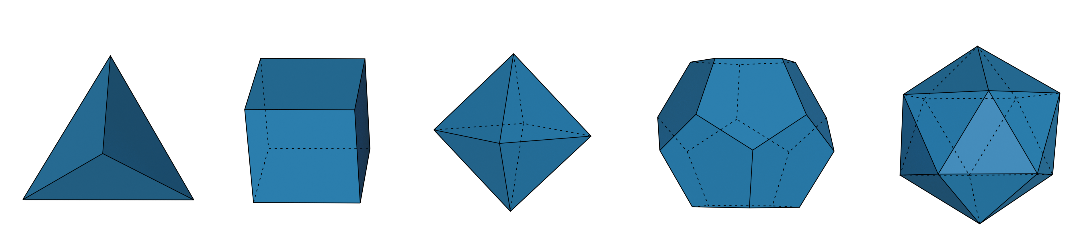
We can simply create platonic solids:
>>> import numpy as np
>>> import ddg.datastructures.halfedge.surface_generator as gen

>>> tetrahedron = gen.tetrahedron()
>>> cube = gen.cube()
>>> octahedron = gen.octahedron()
>>> dodecahedron = gen.dodecahedron()
>>> icosahedron = gen.icosahedron()
or any other polytope from given vertices
>>> conv = gen.convexhull_3d(np.random.random((8, 3)))
It also includes a generator function for an icosphere():
>>> icosphere = gen.icosphere(
...     subdivision_steps=1, radius=1, generate_coordinates=True
... )
and a cylinder()
>>> cylinder = gen.cylinder(
...     resolution=20, fill_caps=True, generate_coordinates=True, co_attr="co"
... )
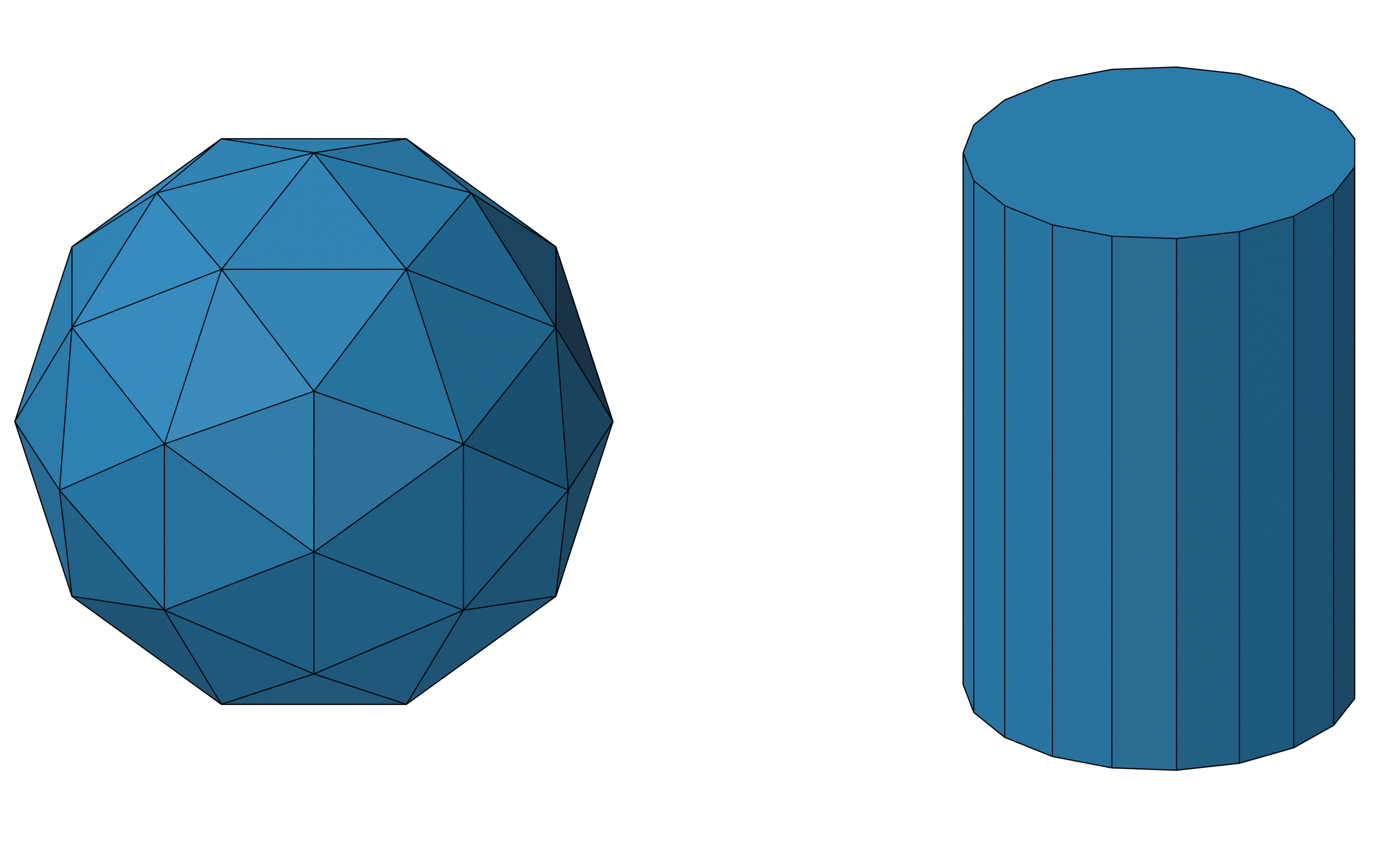
These two are used for the Tubes-and-Spheres visualization of half-edge objects (see Visualization of halfedge objects).
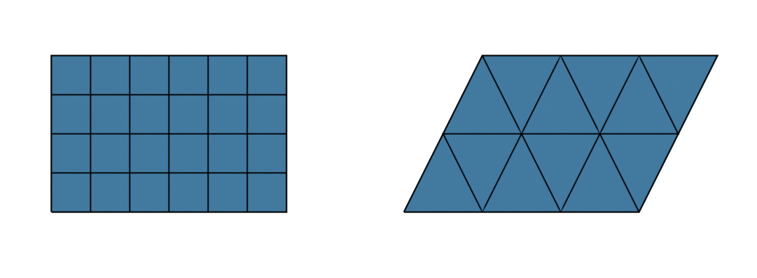
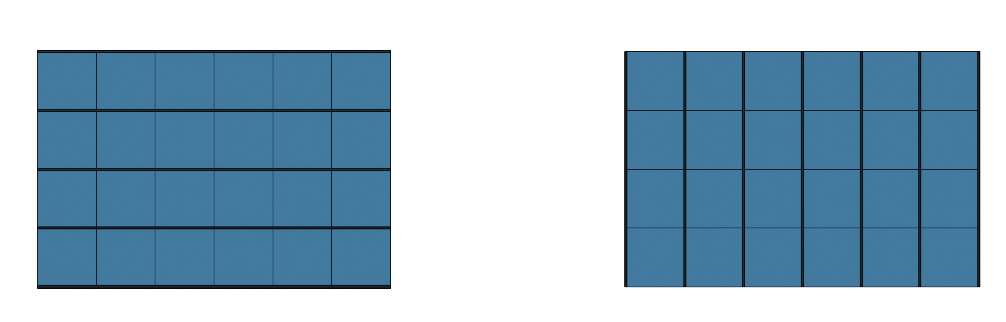
Furthermore, the surface generator allows us to generate grids, which are planar meshes of faces with a fixed number of vertices, as half-edge surfaces:
>>> quad_grid = gen.grid(4, 5)
>>> triangle_grid = gen.triangle_grid(4, 5)
The grid() function for quadrilateral grids has an extra
keyword where vertices can be specified. If vertices are given they are copied to a new surface, keeping their old
attributes. If they have a coordinate attribute co the coordinates stored in this attribute are used, other wise the
generate_coordinate keyword holds. Note that the given dimension must coincide with the number of vertices. 4
For more, see Working with grids.
One can also create an arrow, useful for vector field visualization:
>>> arrow = gen.arrow(resolution=30)
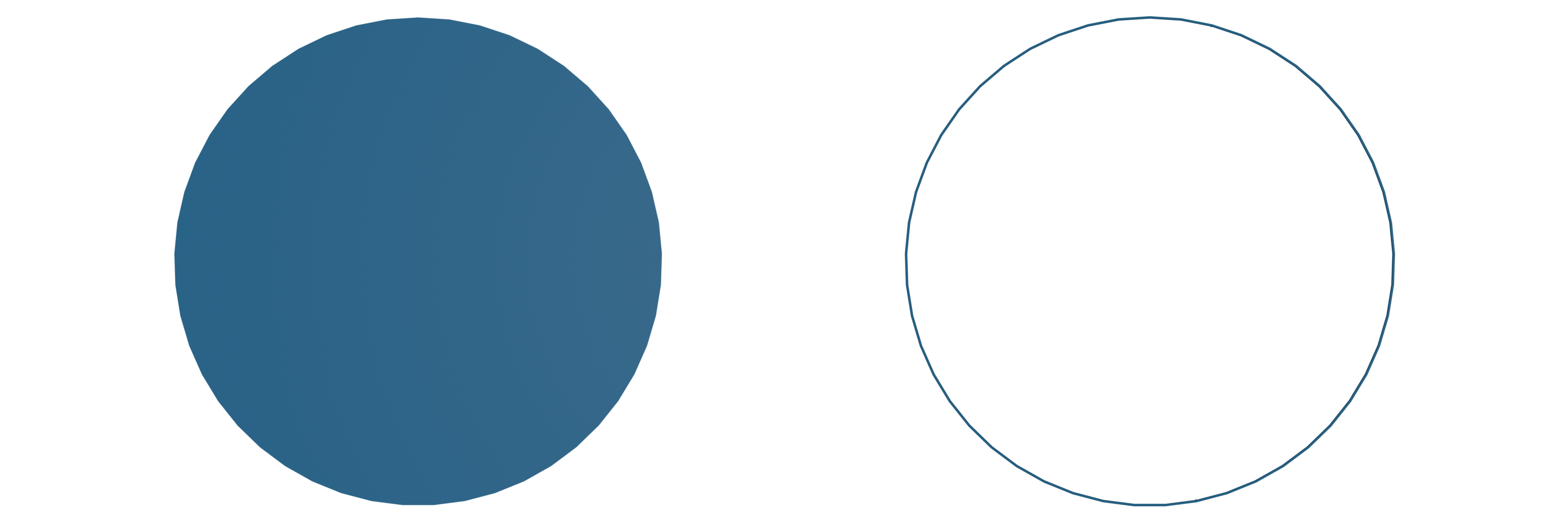
A disc or circle embedded in 3d Euclidean space can be created using
>>> disc = gen.disc(
...     circle_subdivisions=40,
...     generate_coordinates=True,
...     co_attr="co",
...     center=np.array([0, 0, 0]),
...     radius=3,
...     normal=np.array([0, 0, 1]),
... )
>>> circle = gen.disc(
...     circle_subdivisions=40,
...     generate_coordinates=True,
...     co_attr="co",
...     fill_face=False,
...     center=np.array([0, 0, 0]),
...     radius=3,
...     normal=np.array([0, 0, 1]),
... )
Accessing the surfaces’ data
All the information about a half-edge surface is stored in its vertices edges and faces.
Information can be accessed using the ddg.datastructures.halfedge.get module.
We start with a cube:
>>> import ddg.datastructures.halfedge.surface_generator as gen
>>> get = ddg.halfedge.get
>>> cube = gen.cube()
The cells of the surface are stored in classes and we can easily find the number of cells where the class name is extended by the memory address of the surface:
>>> cube.verts
<class 'ddg.datastructures.halfedge._node.Verts...'>
>>> cube.edges
<class 'ddg.datastructures.halfedge._node.Edges...'>
>>> cube.faces
<class 'ddg.datastructures.halfedge._node.Faces...'>

>>> len(cube.verts), len(cube.edges), len(cube.faces)
(8, 24, 6)
These classes are not subscriptable but iterable:
>>> for v in cube.verts:
...     pass
...
Sometimes it is handy to just pick out a single cell:
>>> get.get_vertex(cube)
Verts(index=0, edge=0, surface=...)
>>> get.get_edge(cube)
Edges(index=0, head=0, face=0, surface=...)
>>> get.get_face(cube)
Faces(index=0, edge=0, surface=...)
Functions in the get module that are built to yield multiple
instances of cells will return generators. For example, the following two generators will yield the same edges:
>>> f = get.get_face(cube)
>>> get.get_edges(f)
<generator object get_edge_loop at 0x...>
>>> get.get_edge_loop(f.edge)
<generator object get_edge_loop at 0x...>
If only the number of instances are of interest one can either use the implemented functions or work with list comprehensions:
>>> assert get.get_number_of_edges(f) == get.count_edges_in_loop(f.edge)
>>> assert len([e for e in get.in_edges(v)]) == len([e for e in get.out_edges(v)])
Another handy accessory of this module is dealing with interior and boundary edges.
The functions interior_vertices() and
boundary_vertices() return generators that yield all the desired
vertices. Similar functions exist for edges:
>>> [e.face for e in get.boundary_edges(cube)]
[]
>>> len([e.face for e in get.interior_edges(cube)])
24
They use is_boundary_vertex() and
is_boundary_edge() which return a bool.
Modifying a surface
A great part of working with half-edge sufaces is the modification of a given
surface. These modification can for example include joining, attaching and
glueing or anything about separating, splitting and removing. Next to the
Surface methods
add_vertex(),
add_edge(),
add_face() and
glue(), the half-edge
package allows much simpler and more efficient ways. The module
ddg.datastructures.halfedge.modify contains a variety of
functions to modify a given surface.
In the following we will give a variety of small code snippets and supply pictures of their effects on a given surface. For the creation of the pictures coordinates where explicitly set for vertices, see the next section Adding attributes to vertices, edges and faces. Thus they only serve as a rough orientation, essentially all surfaces in this section are purely combinatoric.
In order to apply various utility functions we always start with the simple surface from the beginning:
>>> from ddg.datastructures.halfedge.surface import Surface
>>> import ddg.datastructures.halfedge.get as get
>>> import ddg.datastructures.halfedge.modify as modify

>>> s = ddg.halfedge.Surface()
>>> f0 = s.add_face(3)
>>> f1 = s.add_face(5)
>>> s.glue(f0.edge, f1.edge)
Removing and adding faces:
>>> modify.remove_face(f1)

>>> boundary = get.boundary_edges(s)

>>> e = next(boundary)
>>> while e.face is not None or e.opp.face is not None:
...     e = next(boundary)
...

>>> f1 = modify.fill_hole(e)
>>> f1
Faces(index=1, edge=6, surface=...)
Note
When calling remove_face() the edge loop that corresponds to the
input face is not deleted. Therefore after removing the face we can find edges of this loop and fill the hole of this
edge loop with a face using fill_hole().
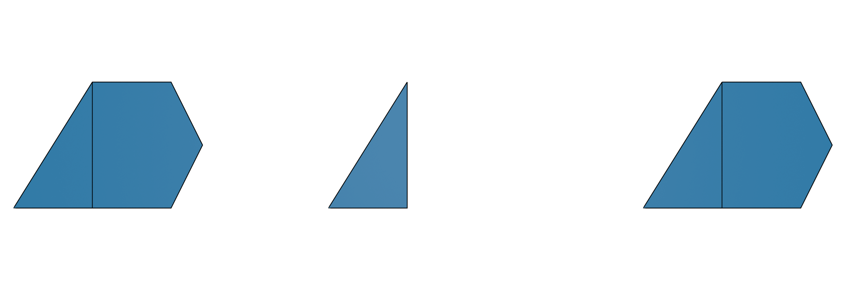
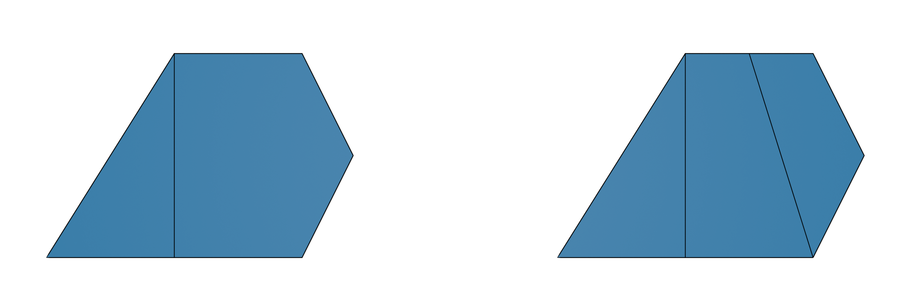
Subdividing and joining faces by hand:
>>> edge = f1.edge.pre
>>> e0, e1, v = modify.subdivide_edge(edge, 2)

>>> new_edge = modify.split_face_at(f1, v[0], f1.edge.nex.head)
>>> modify.join_neighbouring_faces(new_edge)
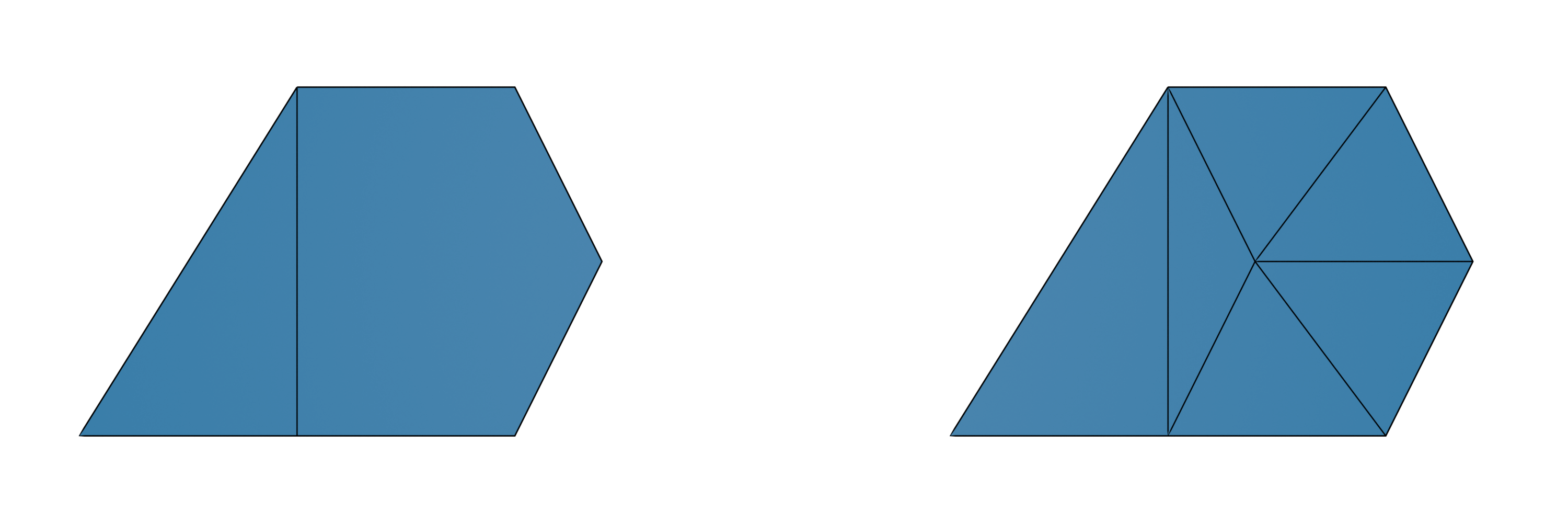
Stellar subdivision using stellar_subdivide():
>>> v = modify.stellar_subdivide(f1)
>>> v
Verts(index=7, edge=11, surface=...)
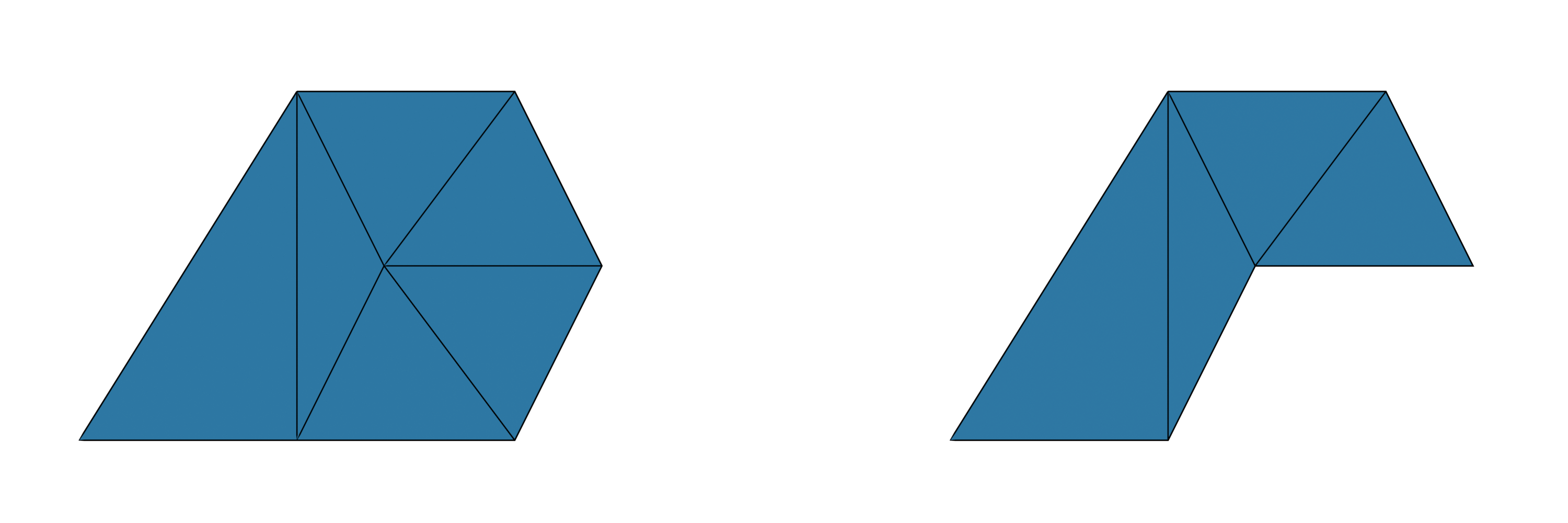
Deleting a vertex along with all its connecting edges and faces using remove_vertex():
>>> v = get.get_vertex(s)
>>> modify.remove_vertex(v)
Extending polygons to 3-dimensional polytopes:
>>> import ddg
>>> s = ddg.halfedge.Surface()
>>> f0 = s.add_face(5)

>>> v = modify.attach_pyramid(f0.edge.opp)
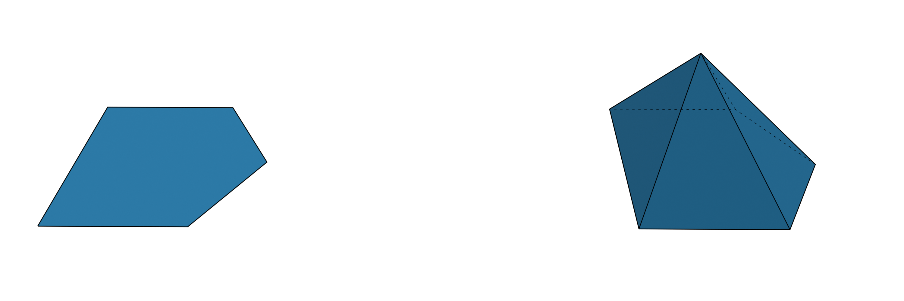
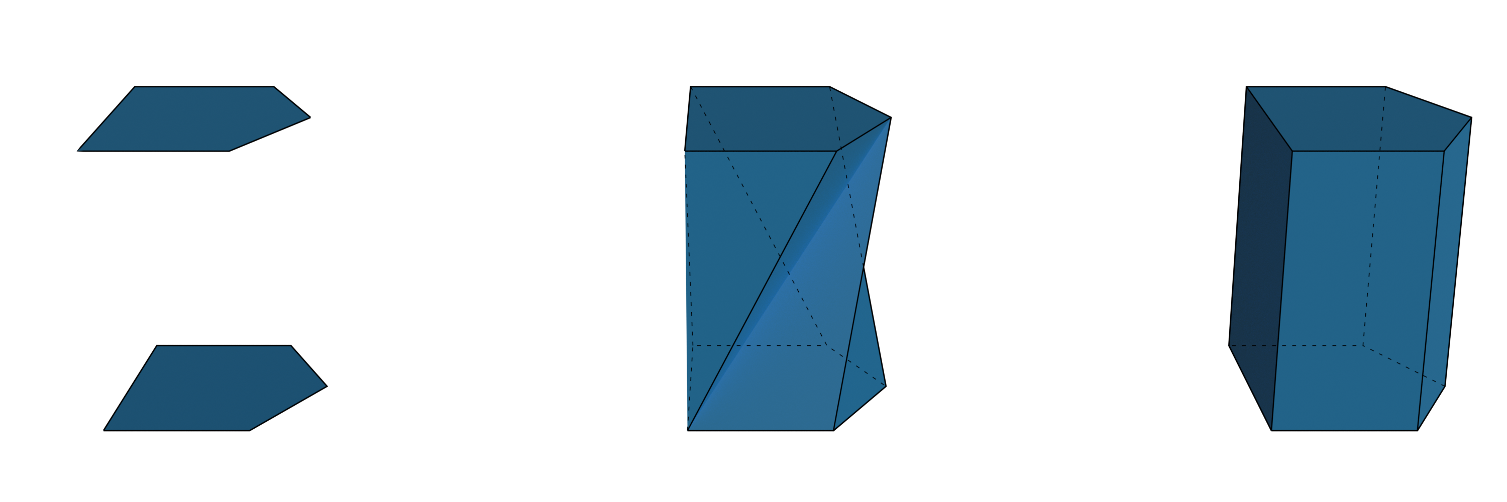
To extend a polygon to a 3-dimensional polytope we can for example use the functions
attach_pyramid() or
bridge_loops():
>>> s = ddg.halfedge.Surface()
>>> f0 = s.add_face(5)
>>> f1 = s.add_face(5)

>>> modify.bridge_loops(f0.edge, f1.edge)
The methods add_vertex()
just adds a single isolated vertex. The function
add_edge() connects two
vertices with a “whole” edge:
>>> s = ddg.halfedge.Surface()
>>> v1 = s.add_vertex()
>>> v2 = s.add_vertex()
>>> e = s.add_edge(v1, v2)
>>> e.head is v2
True
>>> e.opp.head is v1
True
>>> s.validate_curve()
In contrast to the functions mentioned above, these functions will not preserve the manifold property.
Adding attributes to vertices, edges and faces
Adding attributes to vertices, edges and faces of surfaces is an essential part.
New attributes can be initialized using add_attribute of the _node class.
The most commonly used attribute is the "co" attribute for vertices that stores 3-dimensional coordinates of
the corresponding vertices of the surface.
It is possible to name the vertex attribute storing the coordinates differently.
Functions that depend on the coordinate attribute support a keyword argument co_attr="co".
Coordinates can be assigned to the vertices in the following way.:
>>> import ddg

>>> s = ddg.halfedge.Surface()
>>> f0 = s.add_face(3)
>>> f1 = s.add_face(5)
>>> s.glue(f0.edge, f1.edge)

>>> co_attr = s.verts.add_attribute("co")

>>> l = [
...     [0.5, 0, 0],
...     [0.7, 0.4, 0],
...     [0.5, 0.8, 0],
...     [0, 0.8, 0],
...     [-0.5, 0, 0],
...     [0, 0, 0],
... ]

>>> for i, v in enumerate(s.verts):
...     v.co = l[i]
...     # Similarly one could assign the coordinates by
...     # co_attr[v] = l[i]
...
Similarly attributes can be assigned to edges and faces:
>>> s.edges.add_attribute("len")
<ddg.datastructures.halfedge._node.NodeAttribute object at 0x...>
>>> s.faces.add_attribute("is_triangle", False)
<ddg.datastructures.halfedge._node.NodeAttribute object at 0x...>
After the initialization above all edges have a e.len attribute that is by default set to None and all faces have a
f.is_triangle attribute that, by default, is set to False.
Utilities for setting (common) attributes
The module set contains functions to compute and set useful attributes
of halfedge surfaces.
The most general example is setting an attribute computed by a custom function on the desired cells:
set_attr_by_function()
>>> hds = gen.triangle_grid(2, 2)
>>> def neighbouring_faces(face):
...     return len(
...         list(
...             [e for e in get.get_edge_loop(face.edge) if e.opp.face is not None]
...         )
...     )
...
>>> attribute = ddg.halfedge.set.set_attr_by_function(
...     hds,
...     neighbouring_faces,
...     cell_type="faces",
...     attr_name="number_of_neighbouring_faces",
... )
More specific examples are given by set_euclidean_length_attr()
that assigns the euclidean edge length to edges (also see Modifying surfaces with coordinates),
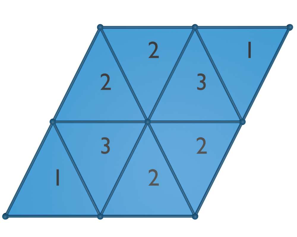
or by set_valency_attr(),
that assigns a valency attribute to either vertices or faces that stores the number of neighbouring cells of the same kind.
To get the same result as in the above example
one can use
>>> attribute = ddg.halfedge.set.set_valency_attr(
...     hds, cell_type="faces", attr_name="number_of_neighbouring_faces"
... )
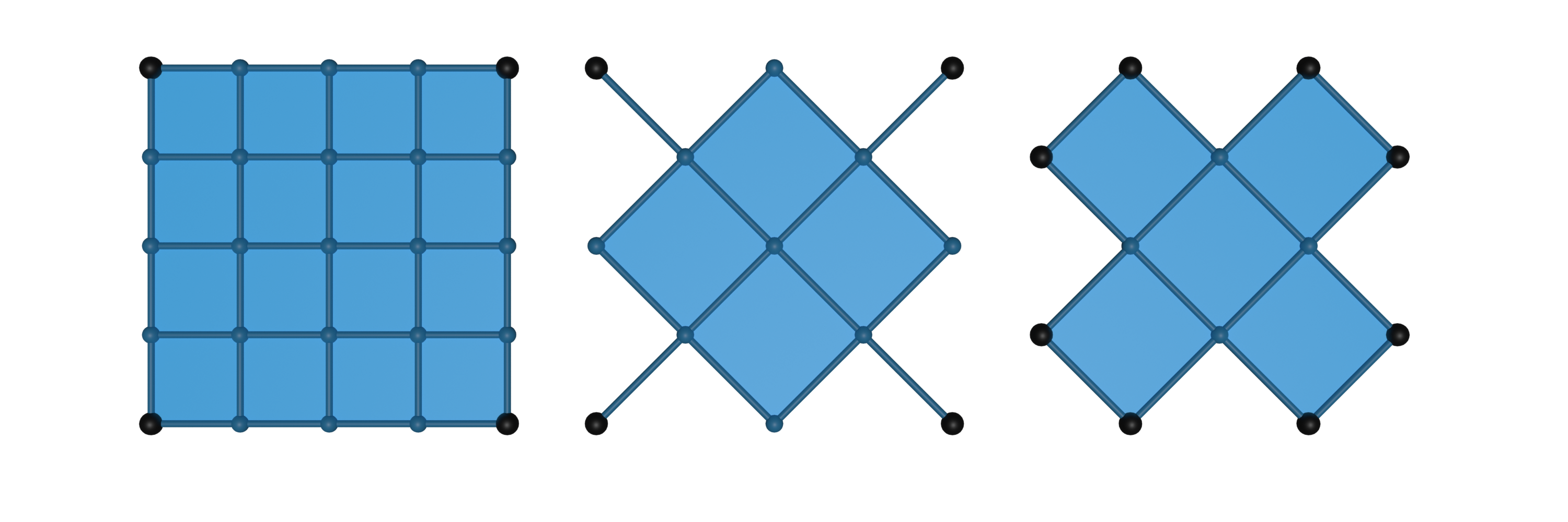
An even more specific example is given by
indicate_minimal_valency(), that can be used to identify the
corners of regular halfedge surface:
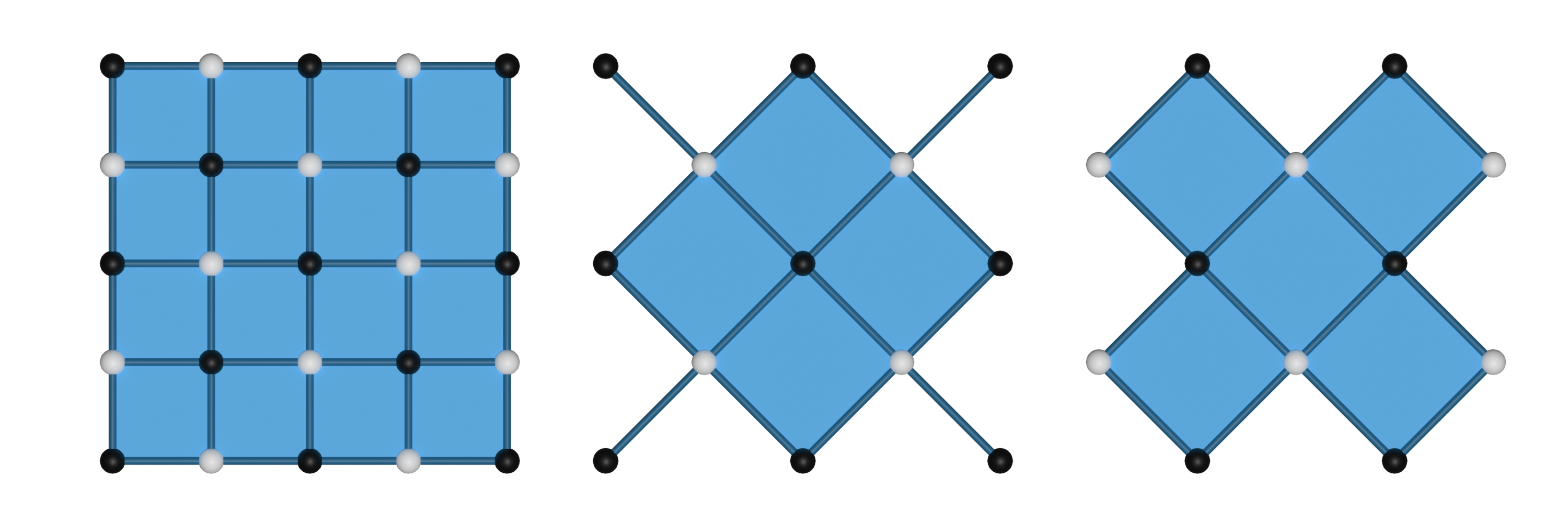
>>> grid = gen.grid(4, 4)
>>> diag_grid1, diag_grid2 = ddg.halfedge.modify.diagonals(grid)

>>> attr1 = ddg.halfedge.set.set_minimal_valency_attr(
...     grid, attr_name="is_corner_vertex", attr_values=[1, 0]
... )
>>> attr2 = ddg.halfedge.set.set_minimal_valency_attr(
...     diag_grid1, attr_name="is_corner_vertex", attr_values=[1, 0]
... )
>>> attr3 = ddg.halfedge.set.set_minimal_valency_attr(
...     diag_grid2, attr_name="is_corner_vertex", attr_values=[1, 0]
... )

>>> len([v for v in grid.verts if attr1[v]])
4
A different utility that can be found in the module
allows simple bi-coloring of hds using bicolor_vertices(),
bicolor_edges() or
bicolor_faces() for a bi-coloring of vertices, edges or
faces, respectively.:
>>> v0, v1 = ddg.halfedge.set.bicolor_vertices(
...     grid, color_attr="color", colors=["white", "black"]
... )
>>> v0, v1 = ddg.halfedge.set.bicolor_vertices(
...     diag_grid1, color_attr="color", colors=["white", "black"]
... )
>>> v0, v1 = ddg.halfedge.set.bicolor_vertices(
...     diag_grid2, color_attr="color", colors=["white", "black"]
... )
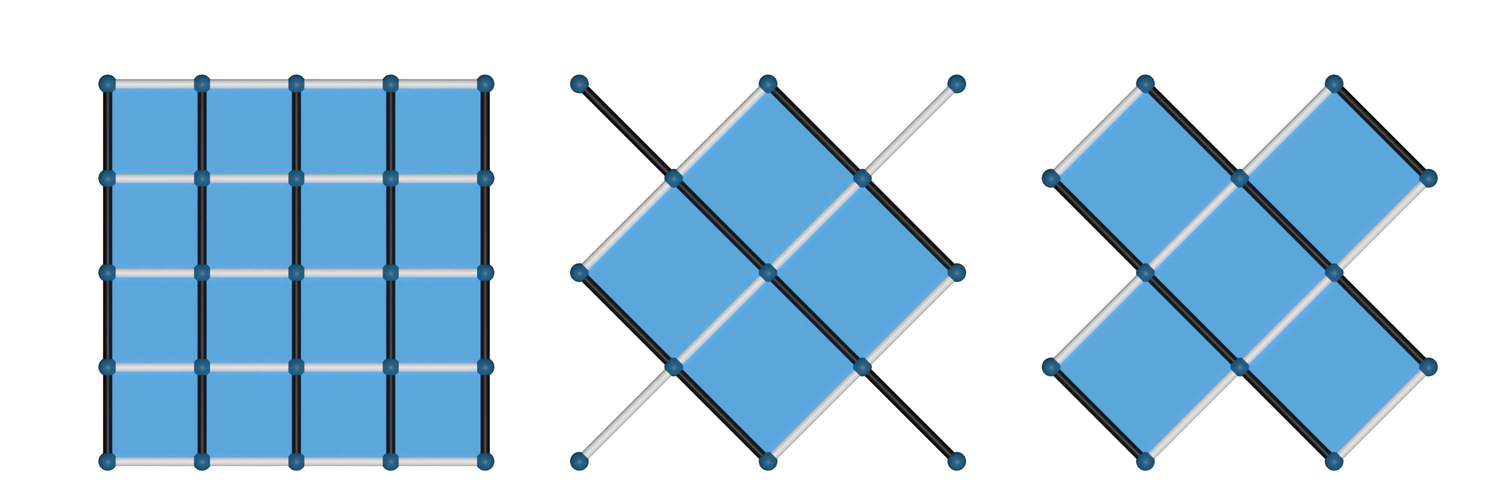
>>> e0, e1 = ddg.halfedge.set.bicolor_edges(
...     grid, color_attr="color", colors=["white", "black"]
... )
>>> e0, e1 = ddg.halfedge.set.bicolor_edges(
...     diag_grid1, color_attr="color", colors=["white", "black"]
... )
>>> e0, e1 = ddg.halfedge.set.bicolor_edges(
...     diag_grid2, color_attr="color", colors=["white", "black"]
... )
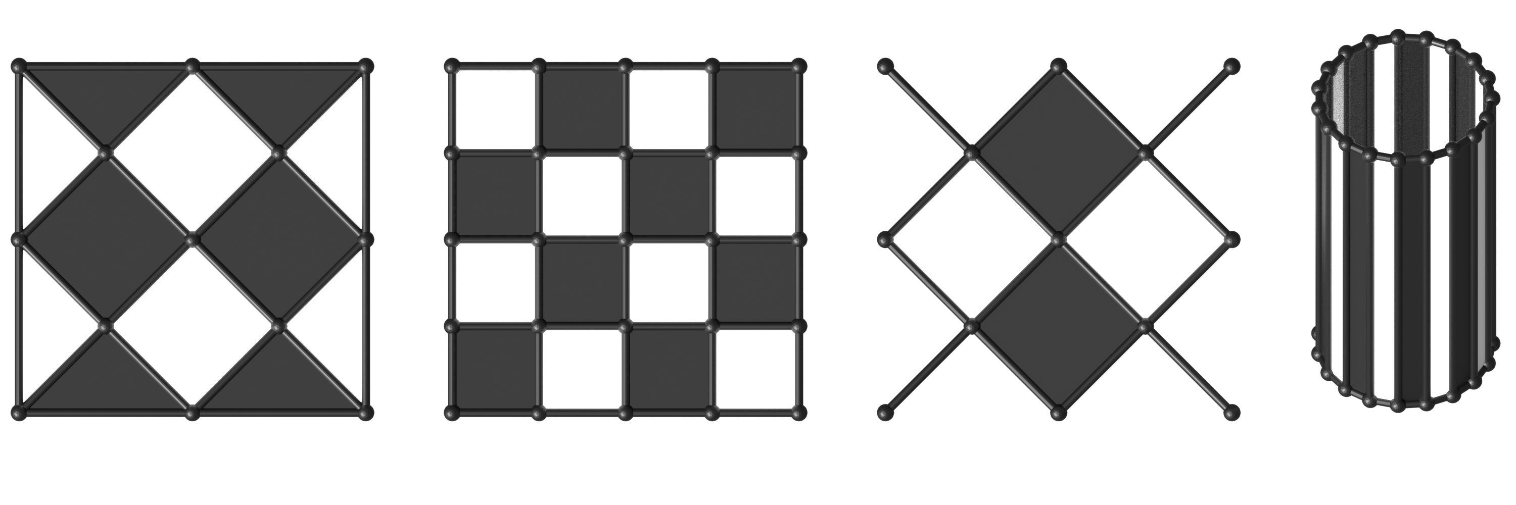
>>> diag_grid_3 = ddg.halfedge.modify.diagonals(grid, boundary_face_incidence=3)[0]
>>> f0, f1 = ddg.halfedge.set.bicolor_faces(
...     diag_grid_3, color_attr="color", colors=["white", "black"]
... )
>>> f0, f1 = ddg.halfedge.set.bicolor_faces(
...     grid, color_attr="color", colors=["white", "black"]
... )
>>> f0, f1 = ddg.halfedge.set.bicolor_faces(
...     diag_grid1, color_attr="color", colors=["white", "black"]
... )
>>> cylinder = gen.cylinder(fill_caps=False)
>>> f0, f1 = ddg.halfedge.set.bicolor_faces(
...     hds, color_attr="color", colors=["black", "white"]
... )
Modifying surfaces with coordinates
In addition to the previously mentioned utilities there are more utility functions that work with surfaces that have
3-dimensional coordinates set on the vertices.
The function set_euclidean_length_attr() computes the Euclidean length
of the edges:
>>> length_attr = ddg.halfedge.set.set_euclidean_length_attr(
...     grid, co_attr="co", attr_name="length"
... )
>>> ddg.halfedge.get.get_edge(grid).length
1.0
By default, the grid possesses 2-dimensional coordinates stored in a vertex attribute with the name co.
With join_colplanar_faces() we can numerically test
whether two adjacent faces are coplanar and if so we can join them:
>>> s = gen.convexhull_3d(
...     [
...         [1, 1, 1],
...         [1, -1, 1],
...         [1, 1, -1],
...         [1, -1, -1],
...         [1, 0, 1.5],
...         [1, 0, -1.5],
...         [1, -1.5, 0],
...         [1, 1.5, 0],
...         [-1, 1, 1],
...         [-1, -1, 1],
...         [-1, 1, -1],
...         [-1, -1, -1],
...     ],
...     False,
... )
>>> len(s.faces)
20
>>> modify.join_coplanar_faces(s)
>>> len(s.faces)
14
In some cases it might be convenient to reverse the orientation of a surface which can be done using the function
reverse_orientation().
Note
The function reverse_orientation() reverses the orientation of
all edges of a surface. It might be convenient to do this for single connected components but it does not make sense
for single faces or edges.
The reverse_orientation() function can, for example, be used to
simplify the visualization process of a surface created by bridge_loops():
>>> s = ddg.halfedge.Surface()
>>> f0 = s.add_face(5)

>>> co_attr = s.verts.add_attribute("co")

>>> l = [[0.5, 0, 0], [0.7, 0.4, 0], [0.5, 0.8, 0], [0, 0.8, 0], [0, 0, 0]]

>>> for k, v in enumerate(ddg.halfedge.get.get_vertices(f0)):
...     v.co = l[k]
...

>>> ddg.halfedge.modify.reverse_orientation(s)

>>> f1 = s.add_face(5)

>>> for k, v in enumerate(ddg.halfedge.get.get_vertices(f1)):
...     l[k][2] += 1
...     v.co = l[k]
...

>>> ddg.halfedge.modify.bridge_loops(f0.edge, f1.edge)
Working with grids
The surface_generator contains a
grid() method that creates a grid of m times n quadrilaterals
and a triangle_grid() method that creates a grid of m times n
triangles.
Various functions to modify grids are located at ddg.datastructures.halfedge.grid.
Creating grids and bi-coloring a quadrilateral grid using bicolor_graph():
>>> grid = gen.grid(6, 4)
>>> triangle_grid = gen.triangle_grid(6, 4)

>>> v0, v1 = ddg.halfedge.set.bicolor_vertices(grid)

>>> v0[0].color, v1[0].color
(0, 1)
The module ddg.datastructures.halfedge.grid includes functions to modify grids.
Finding parallel lines of a quadrilateral grid using get_coordinate_polylines()
and get_coordinate_polyline():
>>> x_lines, y_lines = ddg.halfedge.grid.get_coordinate_polylines(grid)
>>> len(x_lines), len(y_lines)
(5, 7)
>>> x_line = ddg.halfedge.grid.get_coordinate_polyline(
...     ddg.halfedge.get.get_edge(grid)
... )
>>> len(x_line)
4
Creating two grids of diagonal combinatoric to the given grid using
ddg.datastructures.halfedge.modify.diagonals():
>>> diagonal_grid0, diagonal_grid1 = ddg.halfedge.modify.diagonals(
...     grid, boundary_face_incidence=4, append_single_edges=True
... )
>>> diagonal_grid0
<ddg.datastructures.halfedge.surface.Surface object at 0x...>

>>> grid0, grid1 = ddg.halfedge.modify.diagonals(
...     diagonal_grid0, boundary_face_incidence=4, append_single_edges=True
... )
>>> grid0
<ddg.datastructures.halfedge.surface.Surface object at 0x...>
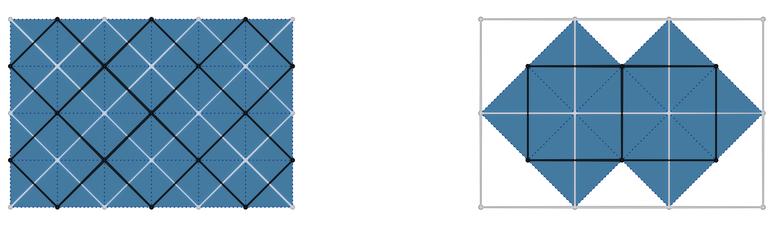
The keyword argument append_single_edges decides whether to attach edges in
the corners of a diagonal grid (making it lose the manifold property). The
keyword argument boundary_face_incidence states how many vertices of
another color must be adjacent to a given boundary vertex in order to create a
face.
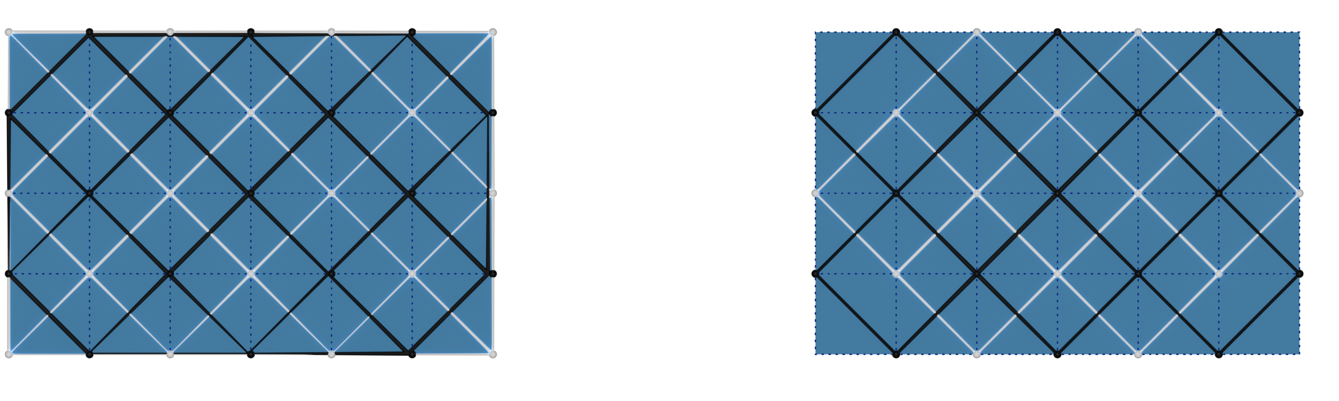
>>> diagonal_grid0, diagonal_grid1 = ddg.halfedge.modify.diagonals(
...     grid, boundary_face_incidence=3, append_single_edges=True
... )
>>> diagonal_grid0, diagonal_grid1 = ddg.halfedge.modify.diagonals(
...     grid, boundary_face_incidence=4, append_single_edges=False
... )
Validating a surface
Especially when modifying a surface explicitly, for example when setting new
heads, predecessors and successors of edges, it makes sense to check from time
to time whether everything has been set correctly. For this, you can use the
methods validate(),
validate_surface(),
validate_curve() and
validate_graph(),
depending on what type of object you want to represent with your halfedge
object. Basically, validate just checks for consistence of nex, opp and
so on, while the others additionally check if the object is a 2d or 1d manifold
or has faces. See the api docs for details.
It is also a very handy tool to use in tests. It can be executed by:
>>> s.validate()
>>> s.validate_surface()
>>> s.validate_curve()
Traceback (most recent call last):
...
ddg.datastructures.halfedge.surface.SurfaceError: Object has faces.
If everything was set up fine the code will continue and otherwise it will raise a SurfaceError. It is also possible to check whether a given surface consists of triangulated faces:
>>> get.is_triangulation(cube)
False
There is also a function to check whether your object is connected:
>>> get.is_connected(cube)
True
Visualization in Blender
A guide on how to visualize halfedge objects in Blender can be found here: Visualizing halfedge objects.